# AllAboutEE 的 ESP8266 伺服器測試 (四) : 完結篇
這個構想來自前陣子所買的一片 Webduino 模組, 參考這篇 :
# 關於 Webduino 開發板
這個 Webduino 是很有創意的產品, 它把 Arduino Pro Mino 與 ESP8266 組成一個物聯網模組, 然後透過把網頁元件包裝起來, 讓不懂 C 語言, 但懂一點網頁設計的人也能很容易地玩 Arduino 創意設計, 實在是網頁設計者的福音. 但是對我這種已經熟悉使用 Arduino IDE 開發的人來說, 卻有點畫蛇添足, 雖然 Web component 我也略懂, 但能直用 C 就不必繞個彎用網頁啦.
其實 Webduino 這塊板子買來到現在都還沒時間玩, 但其電路板配置卻帶給一些啟示. 我對板子佈線蠻有興趣的, 之前製作 ESP8266 轉接板時, 每天回家都在思考如何在洞洞板上完成 Layout. 那陣子每天晚上空閒時都拿烙鐵焊接, 完成了六塊轉接板, 之後就用他們插在麵包板上做實驗, 也在想以後若完成移動偵測+照明控制應用後, 應該學習做個印刷電路板, 畢竟麵包板只適合做原型測試而已. 這個 Webduino 讓我提前有了明確的概念, 就是直接把 Arduino Nano 與 ESP8266 組合在一塊.
經過比對大小, 發現之前做 ESP8266 轉接板的洞洞板剛好合用, 這塊是我在高雄長明街禾樺電子找到的 16*15 + 15*15 的洞洞板, 其寬度足夠放下 Arduino Nano 的兩排 15 支針腳, 長度也剛好可以再放進 ESP8266 與 Wifi 設定切換開關. 注意, 這塊洞洞板分左右兩邊, 雖然看起來像是 duplicate 配置, 好像左右一樣, 其實其中面對焊錫面左邊那塊寬度多一孔, 為 16*15, 左邊那塊是 15*15. 兩塊都可以用, 我是使用 15*16 的, 因為焊錫面要佈線比較容易, 當然 Arduino 針腳數目也剛剛好是每側 15 腳.
首先我用小電鋸將兩塊從中切開 :

切開後兩塊是幾乎一模一樣的單面焊錫洞洞板, 它的四個角有大圓孔, 方便將電路板鎖在機殼上, 也可以用銅柱或塑膠螺絲將多層板疊起來 :

我仿照 Webduino 的布局方式, Arduino Nano 與 ESP8266 要分別插在 15*1 與 2*4 的排母上. 於是周一晚上趁拿龍角散去珍寶給左營阿姨之便, 到禾樺買了兩排可折斷的 15*1 排母 (2*4 的家裡還有), 然後把他們擺放在洞洞板上評估布局方式, 以便接下來安排如何佈線, 這是將來板子的長相 (還沒焊, 只是擺上去而已) :


這裡 Nano 插座旁邊我兩側又各加一排 15*1 排母, 以便能接出 Nano 的接腳連接感測器用. 其實我應該買 15*2 的排母才對, 這樣就不用兩個 15*1 拼成一組 15*2 了. 為了佈線規劃, 我使用 Google 雲端硬碟的繪圖功能描繪了這塊洞洞板, 印出來後就可以用鉛筆在上面嘗試找出最佳佈線方式 :

15*15

16*15
洞洞板正面 (無焊錫面) 元件配置如下, 其中 Nano 的 USB 朝左 :

正面

反面
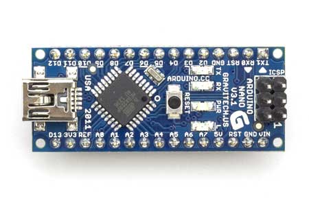

# Arduino Nano規格簡介
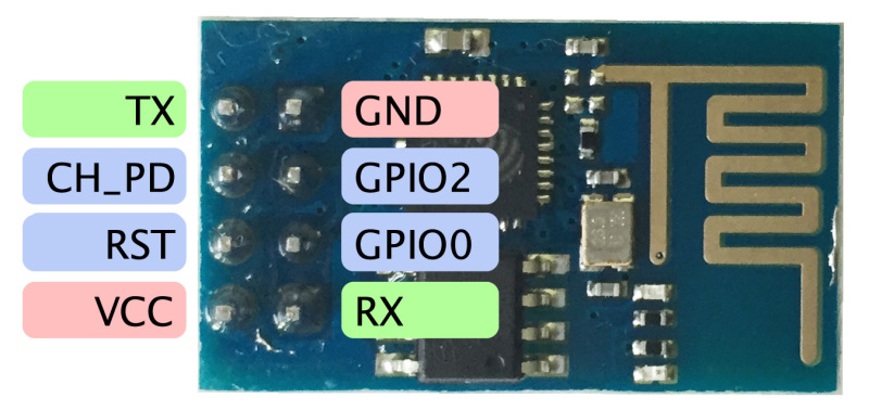
ESP8266 的接腳圖如下 (UXTD=TX, URXD=RX) :


# ESP8266 Introduction
# ESP8266 WiFi 模組 AT command 測試
這塊洞洞板雖然合用, 但是有一個地方需要加工一下, 就是用來引出 Nano 上方接腳 (D0~D12與 RST, GND) 的排母無法插入洞裡, 因為上方第二排左右各少一個洞. 解決辦法當然就是左右用小電鑽個補上一個洞, 或者在上方左右兩個大洞的下緣往下擴張一些, 可讓針腳插進去就可以了, 如下圖所示 :

接下來是背面焊錫面的佈線設計, 也是最麻煩之處. 電路圖是根據前一篇 ESP8266 伺服器測試所用電路修改而來, 因為根據上面 Nano 的接腳圖, 發現我習慣定義為軟體串列埠的 D10(RX) 與 D11(TX) 腳分別是 SPI 通訊要用到的 SS 與 MOSI 腳, 為了避免衝突, 我改挑沒有預設特定用途的 D7(RX) 與 D8 (TX) 當作軟體序列埠, 而 D4 則當模式選擇埠. 所以電路圖修改為如下 :


正面

反面

正面 (有蜂鳴器 Jumper)

反面 (有蜂鳴器 Jumper)
- 先將 Nano 的兩排 2*15 排母, ESP8266 的 2*4 排母, 插零件的 2*4 排母等母座先用三秒膠稍微固定在板子上, 然後再焊接固定. 注意, 三秒膠只要一點點能固著即可, 不要擠太多以免流入插槽裏面, 這樣會讓針腳插不進去.
- 將三個電阻與蜂鳴器, 1*2 排針用三秒膠稍微固定後焊接, 焊好後剪掉電阻與蜂鳴器過長的鐵線, 尤其是電阻的鐵線要留下來作為跨焊的橋接器. 注意, 蜂鳴器有極性, 長腳為正, 短腳接地.
- 焊滑動開關與 AMS1117, 它的 GND (左) 與 Vin (右) 剛好與 Nano 的 GND 與 +5V 相對, 直接跨焊連接.

- 先焊佈線圖中的黃色線路部分, 再焊需要包覆線的跳線部分.

完成後的焊接面如下 :

完成後的側面圖如下 :


看起來還真不錯, 比用麵包板小了一半, 而且不需要再用杜邦線跳線了. 我先用三用電表量看看焊接面的各個接點是否連通或不連通 (切換滑動開關), 特別是 ESP8266 的 3.3V, GND 與 CH_PD 是否都有接通.
接下來就是通電測試, 接到電腦 USB 送電後, 燈號顯示正常, 看來焊線應該沒問題. 然後我把前文程式中的軟體序列埠腳位從 (10,11) 改為 (7,8), 以便符合硬體接線, 參考 :
# AllAboutEE 的 ESP8266 伺服器測試 (四) : 完結篇
#include <SoftwareSerial.h>
#define DEBUG true
SoftwareSerial esp8266(7,8); //(RX,TX)
const int SW_PIN=4; //Pin to switch configuration or working mode
const int MAX_PAGE_NAME_LEN=48; //buffer size
char buffer[MAX_PAGE_NAME_LEN + 1]; //store page_name/ssid/pwd
int mode; //store current mode(LOW=configuration, HIGH=working)
void setup() {
Serial.begin(9600);
esp8266.begin(9600);
sendData("AT+RST\r\n",2000,DEBUG); // reset ESP8266
pinMode(SW_PIN, INPUT);
mode=digitalRead(SW_PIN);
if (mode==LOW) { //wifi configuration mode :
sendData("AT+CWMODE=3\r\n",1000,DEBUG); //configure as access point
sendData("AT+CIPMUX=1\r\n",1000,DEBUG); //enable multiple connections
sendData("AT+CIPSERVER=1,80\r\n",1000,DEBUG); //turn on server 80 port
sendData("AT+CIFSR\r\n",1000,DEBUG); //get ip address
}
else {
sendData("AT+CWMODE=1\r\n",1000,DEBUG); // configure as station
}
}
void loop() {
if (mode==LOW) {setupWifi();}
else { //application codes are here
sendData("AT+CIFSR\r\n",1000,DEBUG);
delay(1000);
}
}
void setupWifi() {
if (esp8266.available()) { // check if the esp is sending a message
if (esp8266.find("+IPD,")) {
delay(1000);
//esp8266 link response : +IPD,0,498:GET / HTTP/1.1
//retrieve connection ID from response (0~4, after "+IPD,")
int connectionId=esp8266.read()-48; //from ASCII to number
//subtract 48 because read() returns ASCII decimal value
//and in ASCII, "0" (the first decimal number) starts at 48
if (esp8266.find("GET /")) { //retrieve page name (router)
memset(buffer, 0, sizeof(buffer)); //clear buffer (all set to 0)
if (esp8266.readBytesUntil('/', buffer, sizeof(buffer))) {
if (strcmp(buffer, "update") == 0) { //update wifi
//"?ssid=aaa&pwd=bbb HTTP/1.1"
esp8266.find("?ssid="); //skip ssid token
memset(buffer, 0, sizeof(buffer)); //clear buffer (all set to 0)
esp8266.readBytesUntil('&', buffer, sizeof(buffer)); //retrieve ssid
String ssid=buffer;
esp8266.find("pwd="); //skip pwd token
memset(buffer, 0, sizeof(buffer)); //clear buffer (all set to 0)
esp8266.readBytesUntil(' ', buffer, sizeof(buffer)); //retrieve pwd
String pwd=buffer;
//configure as a station
String res=sendData("AT+CWJAP=\"" + ssid + "\",\"" + pwd + "\"\r\n",6000,DEBUG);
//show setup result
String webpage="<html>Wifi setup ";
if (res.indexOf("OK") != -1) {webpage += "OK!</html>";}
else {webpage += "Failed!</html>";}
String cipSend = "AT+CIPSEND=";
cipSend += connectionId;
cipSend += ",";
cipSend +=webpage.length();
cipSend +="\r\n";
sendData(cipSend,1000,DEBUG);
sendData(webpage,2000,DEBUG);
String closeCommand = "AT+CIPCLOSE=";
closeCommand+=connectionId; // append connection id
closeCommand+="\r\n";
sendData(closeCommand,3000,DEBUG);
}
else { //show setup page
String webpage="<html><form method=get action='/update/'>SSID ";
webpage += "<input name=ssid type=text><br>";
String cipSend = "AT+CIPSEND=";
cipSend = "AT+CIPSEND=";
cipSend += connectionId;
cipSend += ",";
cipSend +=webpage.length();
cipSend +="\r\n";
sendData(cipSend,1000,DEBUG);
sendData(webpage,2000,DEBUG);
webpage="PWD <input name=pwd type=text> ";
cipSend = "AT+CIPSEND=";
cipSend += connectionId;
cipSend += ",";
cipSend +=webpage.length();
cipSend +="\r\n";
sendData(cipSend,1000,DEBUG);
sendData(webpage,2000,DEBUG);
webpage="<input type=submit value=Connect></form></html>";
cipSend = "AT+CIPSEND=";
cipSend += connectionId;
cipSend += ",";
cipSend +=webpage.length();
cipSend +="\r\n";
sendData(cipSend,1000,DEBUG);
sendData(webpage,2000,DEBUG);
String closeCommand = "AT+CIPCLOSE=";
closeCommand+=connectionId; // append connection id
closeCommand+="\r\n";
sendData(closeCommand,3000,DEBUG);
}
}
}
}
}
}
String sendData(String command, const int timeout, boolean debug) {
String response="";
esp8266.print(command); // send the read character to the esp8266
long int time=millis();
while ((time+timeout) > millis()) {
while(esp8266.available()) {
// The esp has data so display its output to the serial window
char c=esp8266.read(); // read the next character.
response += c;
}
}
if (debug) {Serial.print(response);}
return response;
}
程式上傳後測試 OK, 切換滑動開關至設定模式重開機可順利透過手機瀏覽器設定要連線的無線基地台 SSID 與 PWD, 切換滑動開關至工作模式重開機, 從序列埠監控視窗可看到順利從 DHCP 獲得了一個區網 IP.
終於大功告成囉!
以下是本次製作此模組的零件表與成本概算 :
Arduino Nano 79 元*1=79
ESP8266 ESP-01 79元*1=90
洞洞板 15 元*1=15
3P2段滑動開關 6 元*1=6
蜂鳴器 5 元*1=5
2*4P 排母 5 元*2=10
2*15P 排母 10 元*2=20
1K/2K/10K 電阻 1 元
塑膠螺帽 M3 1 元*4=4
塑膠圓頭螺絲 3-306 1 元*4=4
三秒膠 15 元*1=15
合計 249 元
2016-06-11 補充 :
我將上面的程式做了小部分修改 (主要是 remark), 在應用程式部分我改成可在序列埠監控視窗對 ESP8266 下 AT 指令的程式碼, 作為開發範本 :
#include <SoftwareSerial.h>
#define DEBUG true
//system use please do not edit
SoftwareSerial esp8266(7,8); //(RX,TX)
const int SW_PIN=4; //Pin to switch configuration or working mode
const int MAX_PAGE_NAME_LEN=48; //buffer size
char buffer[MAX_PAGE_NAME_LEN + 1]; //store page_name/ssid/pwd
int mode; //store current mode(LOW=configuration, HIGH=working)
//-----application global variables & constants listed here-----
void setup() {
//system use please do not edit
Serial.begin(9600);
esp8266.begin(9600);
sendData("AT+RST\r\n",2000,DEBUG); // reset ESP8266
pinMode(SW_PIN, INPUT);
mode=digitalRead(SW_PIN);
if (mode==LOW) { //wifi configuration mode :
sendData("AT+CWMODE=3\r\n",1000,DEBUG); //configure as access point
sendData("AT+CIPMUX=1\r\n",1000,DEBUG); //enable multiple connections
sendData("AT+CIPSERVER=1,80\r\n",1000,DEBUG); //turn on server 80 port
}
else {
sendData("AT+CWMODE?\r\n",1000,DEBUG);
sendData("AT+CIPMUX?\r\n",1000,DEBUG);
delay(3000);
}
sendData("AT+CIFSR\r\n",1000,DEBUG); //get ip address
//-----application setup codes listed here-----
}
void loop() {
if (mode==LOW) {setupWifi();}
else { //-----application codes listed here-----
//show ESP8266 response char to serial monitor window
if (esp8266.available()) {Serial.write(esp8266.read());}
//send char to ESP8266 if got char from serial monitor window
if (Serial.available()) {esp8266.write(Serial.read());}
}
}
void setupWifi() {
if (esp8266.available()) { // check if the esp is sending a message
if (esp8266.find("+IPD,")) {
delay(1000);
//esp8266 link response : +IPD,0,498:GET / HTTP/1.1
//retrieve connection ID from response (0~4, after "+IPD,")
int connectionId=esp8266.read()-48; //from ASCII to number
//subtract 48 because read() returns ASCII decimal value
//and in ASCII, "0" (the first decimal number) starts at 48
if (esp8266.find("GET /")) { //retrieve page name (router)
memset(buffer, 0, sizeof(buffer)); //clear buffer (all set to 0)
if (esp8266.readBytesUntil('/', buffer, sizeof(buffer))) {
if (strcmp(buffer, "update") == 0) { //update wifi
//"?ssid=aaa&pwd=bbb HTTP/1.1"
esp8266.find("?ssid="); //skip ssid token
memset(buffer, 0, sizeof(buffer)); //clear buffer (all set to 0)
esp8266.readBytesUntil('&', buffer, sizeof(buffer)); //retrieve ssid
String ssid=buffer;
esp8266.find("pwd="); //skip pwd token
memset(buffer, 0, sizeof(buffer)); //clear buffer (all set to 0)
esp8266.readBytesUntil(' ', buffer, sizeof(buffer)); //retrieve pwd
String pwd=buffer;
//configure as a station
String res=sendData("AT+CWJAP=\"" + ssid + "\",\"" + pwd + "\"\r\n",6000,DEBUG);
//show setup result
String webpage="<html>Wifi setup ";
if (res.indexOf("OK") != -1) {webpage += "OK!</html>";}
else {webpage += "Failed!</html>";}
String cipSend="AT+CIPSEND=";
cipSend += connectionId;
cipSend += ",";
cipSend +=webpage.length();
cipSend +="\r\n";
sendData(cipSend,1000,DEBUG);
sendData(webpage,2000,DEBUG);
String closeCommand = "AT+CIPCLOSE=";
closeCommand+=connectionId; // append connection id
closeCommand+="\r\n";
sendData(closeCommand,3000,DEBUG);
}
else { //show setup page
String webpage="<html><form method=get action='/update/'>SSID ";
webpage += "<input name=ssid type=text><br>";
String cipSend = "AT+CIPSEND=";
cipSend += connectionId;
cipSend += ",";
cipSend +=webpage.length();
cipSend +="\r\n";
sendData(cipSend,1000,DEBUG);
sendData(webpage,2000,DEBUG);
webpage="PWD <input name=pwd type=text> ";
cipSend = "AT+CIPSEND=";
cipSend += connectionId;
cipSend += ",";
cipSend +=webpage.length();
cipSend +="\r\n";
sendData(cipSend,1000,DEBUG);
sendData(webpage,2000,DEBUG);
webpage="<input type=submit value=Connect></form></html>";
cipSend = "AT+CIPSEND=";
cipSend += connectionId;
cipSend += ",";
cipSend +=webpage.length();
cipSend +="\r\n";
sendData(cipSend,1000,DEBUG);
sendData(webpage,2000,DEBUG);
String closeCommand = "AT+CIPCLOSE=";
closeCommand+=connectionId; // append connection id
closeCommand+="\r\n";
sendData(closeCommand,3000,DEBUG);
}
}
}
}
}
}
String sendData(String command, const int timeout, boolean debug) {
String response="";
esp8266.print(command); // send the read character to the esp8266
long int time=millis();
while ((time+timeout) > millis()) {
while(esp8266.available()) {
// The esp has data so display its output to the serial window
char c=esp8266.read(); // read the next character.
response += c;
}
}
if (debug) {Serial.print(response);}
return response;
}
上傳後測試確實可在序列埠監視視窗對 ESP8266 下 AT 指令.
Arduino Nano 的 Pinout :
D12 D11 D10 D9 D8 D7 D6 D5
D4 D3 D2 GND RST RX TX
D13 3V3 AREF A0 A1 A2 A3 A4
A5 A6 A7 +5V RST GND AIN
2016-08-27 補充 :
# 製作 Arduino Nano + ESP8266 物聯網模組 (四) : 完結篇
2017-11-15 補充 :
我目前已經很少用上面製作的板子了, 因為簡單的 2 GPIO 應用我都直接使用 ESP-01 模組, 也是使用 Arduino IDE 以 C 語言開發; 但超過 2 個 GPIO 的應用則改用 D1 Mini, 使用 MicroPython 開發, 基本上我是朝向以 Python 為中心的軟體開發方向走. 不過 Arduino + ESP8266 組合的 IoT 開發板仍有其價值, 例如 Arduino 超多的 GPIO 與 ADC 腳, 這就不是只有一個 ADC 的 D1 mini 與根本沒有接出 ADC 的 ESP-01 模組可比的了.
3 則留言 :
謝謝分享,如果能再加一個溫度sensor 就變成一個temp web server。
請問大大您是用什麼電路布局軟體??謝謝啦
這純粹是用 Google 雲端硬碟裡的簡報功能手繪的喔!
張貼留言